COMPUTATIONAL MODELLING
Computational Modelling
Development of UMAT (User subroutine) for anisotropic hyperelastic model in Abaqus and constitutive law for collagen fibre damage
This tutorial paper provides a step-by-step guide to developing a comprehensive understanding of the different forms of the deformation gradient used in Abaqus, and outlines a number of key issues that must be considered when developing an Abaqus user defined material subroutine (UMAT) in which the Cauchy stress is computed from the deformation gradient.
We outline the key steps that must be implemented in developing an anisotropic fibre-reinforced hyperelastic UMAT for use with continuum elements and local orientation systems. We also demonstrate that a classical local deformation gradient is provided by Abaqus/Standard if structural (shell and membrane) elements are used, and by Abaqus/Explicit for all element types. This paper has worked examples that can be found at the following link : https://zenodo.org/record/3546010#.Y_8evXbP2Uk
Reference
Nolan, D. R., Lally, C., & McGarry, J. P. (2022). Understanding the deformation gradient in Abaqus and key guidelines for anisotropic hyperelastic user material subroutines (UMATs). Journal of the Mechanical Behavior of Biomedical Materials, 126. https://doi.org/10.1016/j.jmbbm.2021.104940
Further work has look at the role of damage constituents in damage accumulation in arterial tissue and constitutive model development. In this paper, a constituent specific study was performed to investigate the role of the ground matrix and collagen fibres of arterial tissue in response to supra-physiological loads. Cyclic mechanical tests were conducted on intact and collagenase-digested strips of porcine common carotid arteries. Using these tests, four passive damage-relevant phenomena were studied, namely (i) Mullins effect, (ii) hysteresis, (iii) permanent set and (iv) matrix failure and fibre rupture. A constitutive model was also developed to capture all of these damage-relevant phenomena using a continuum damage mechanics approach. The implemented constitutive model was fit to experimental results for both intact and digested samples.

Figure (1): A schematic of uniaxial mechanical tests simulated for specimens in a circumferential and b axial directions by applying the displacements boundary condition (u) in Abaqus

Figure (2): A schematic presentation of the implemented inverse FE algorithm for material calibration of the media layer of porcine carotid arteries in Isight. Different parameterized Abaqus input files have been designated for the specimens in the axial and circumferential directions. The input files were imported into the Abaqus component of Isight and the material parameters selected as optimization variables. The results from the experiments and simulation have been imported into the data matching component where the sum of the stress difference for 100 points on each loading and reloading path has been defined as objective functions separately for samples in axial and circumferential directions. A hybrid optimization algorithm was then performed to characterize the material parameters of each specimen

Figure 3: Cyclic uniaxial tension tests of the intact media of two porcine common carotid arteries in the axial and circumferential directions
References
Ghasemi, M., Nolan, D. R., & Lally, C. (2018). An investigation into the role of different constituents in damage accumulation in arterial tissue and constitutive model development. Biomechanics and Modeling in Mechanobiology, 17(6), 1757–1769. https://doi.org/10.1007/s10237-018-1054-3
Establishment of computational methods for more robust stress analysis
In this study, we investigate how the estimated material parameters and overall stress distributions geometries of carotid bifurcations, extracted from in-vivo MR images, alter with the inclusion of the zero-pressure configuration and residual stress. This approach consists of the following steps: (1) geometry segmentation and hexahedral meshing from in-vivo magnetic resonance images (MRI) at two known phases; (2) computation of the zero-pressure configuration and the associated residual stresses; (3) minimization of an objective function built on the difference between the stress states of an “almost true” stress field at two known phases and a “deformed” stress field by altering the input material parameters to determine patient-specific material properties; and (4) comparison of the stress distributions throughout these carotid bifurcations for all cases with estimated material parameters. This numerical approach provides insights into the need for estimation of both the zero-pressure configuration and residual stress for accurate material property estimation and stress analysis for the carotid bifurcation, establishing the need for these methods to be implemented to increase the reliability of stress as a rupture risk metric

FIGURE 1(A) Delineation of vessel from T2 weighted MRI images and creation of 3D stack (B) Initial model created–determining the location of sharp edges and smoothing the geometry (C) Surfaces of new smoothed surface are extracted and volume model is created for export into mesh pre-processor (D) Hexa-block tool used to define the geometry and create hexahedral finite element meshes of the bifurcation

FIGURE 2 (A) Locations across the bifurcation for theoretical approximation of the circumferential stress (B) Inclusion of the residual stress at the common (CCA), external (ECA) and internal (ICA) carotid artery (C) Inclusion of residual stresses in the bifurcation model looking at the fiber stress T1(kPa) over the normalized radius (mm) after applying 0, 5, 10 and 15 smoothing loops (D) Impact of inclusion of residual stresses on the maximum principal stress (kPa) after applying 0, 5, 10 and 15 smoothing loops

FIGURE 3(A) Simulated stress result for Case1(B) Simulated stress result for Case2(C) Simulated stress result for Case3(D) Simulated stress result for Case4(E) Single element test of estimated material parameters under uniaxial tension (F) Percentage of volume graph for the four cases showing the stress distribution throughout the vessel wall

Johnston, R. D., Ghasemi, M., & Lally, C. (2023). Inverse material parameter estimation of patient-specific finite element models at the carotid bifurcation: The impact of excluding the zero-pressure configuration and residual stress. International Journal for Numerical Methods in Biomedical Engineering, 39(1). https://doi.org/10.1002/cnm.3663
Determining possible in-silico diagnostic measures for plaque rupture vulnerability
In this study, a local stress modulated remodelling algorithm is proposed to explore the mechanical response of arterial tissue to the remodelling of collagen fibres. This stress driven remodelling algorithm is used to predict the optimum distribution of fibres in healthy and diseased human carotid bifurcations obtained using Magnetic Resonance Imaging (MRI). In the models, healthy geometries were segmented into two layers: media and adventitia and diseased into four components: adventitia, media, plaque atheroma and lipid pool (when present in the MRI images). A novel meshing technique for hexahedral meshing of these geometries is also demonstrated. Using the remodelling algorithm, the optimum fibre patterns in various patient specific plaques are identified and the role that deviations from these fibre configurations in plaque vulnerability is shown. This study provides critical insights into the collagen fibre patterns required in carotid artery and plaque tissue to maintain plaque stability.

Figure (1) A healthy carotid bifurcation cross sectioned using planes(A–C).(B) Presentation of the directions of the maximum and intermediate principal stresses in each cross section along with the angle and dispersion of fibres. The angle of fibres (α)is presented with respect to the direction of the maximum principal stress
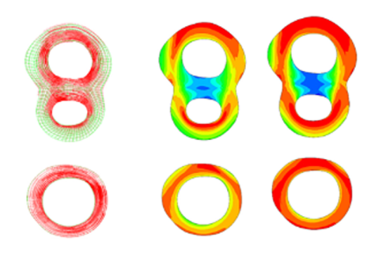
Figure (2): Left image - The values obtained for the remodelling metric (RM) during the remodelling process. Right image - The values of the remodelling metric for the three different cases at cross sections of the diseased bifurcation corresponding to the first plane of Figure 9.(B)The values of the remodelling metric for the three different cases at cross sections of the diseased bifurcation corresponding to the second plane of Figure 9.(C)The values of the remodelling metric for the three different cases at cross sections of the diseased bifurcation corresponding to the third plane of Figure 9
 Patient specific geometry preparation steps. Section the geometry and extraction of the curves part (A) and (B) respectively. (C) skin the inner surface, (D) skin the outer surface and (E) stitching the geometry surfaces where required (red curve)

Orientation of collagen fibres (A) without axial strain and (B) with applied axial strain of 10% under blood pressure of 16 kPa.